Learning Examples | Foundations | Hacking | Links
Examples > Sensors
ADXL3xx Accelerometer
This tutorial shows you how to read an Analog Devices ADXL3xx series (e.g. ADXL320, ADXL321, ADXL322, ADXL330) accelerometer and communicate the acceleration to the a personal computer.
This tutorial was built using the breakout boards from Sparkfun. The adafruit accelerometer breakout board also works, though it must be wired differently.
The ADXL3xx outputs the acceleration on each axis as an analog voltage between 0 and 5 volts. To read this, all you need is the analogRead() function.
Hardware Required
- Arduino Board
- ADXL3xx Accelerometer
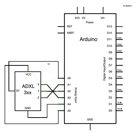
Circuit
The accelerometer uses very little amperage, so it can be plugged into your Arduino and run directly off of the output from the Arduino's digital output pins. To do this, you'll use three of the analog input pins as digital I/O pins, for power and ground to the accelerometer, and for the self-test pin. You'll use the other three analog inputs to read the acclerometer's analog outputs.
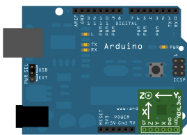
image developed using Fritzing. For more circuit examples, see the Fritzing project page
Schematic:
click the image to enlarge
Here are the pin connections for the configuration shown above:
| Breakout Board Pin | Self-Test | Z-Axis | Y-Axis | X-Axis | Ground | VDD |
| Arduino Analog Input Pin | 0 | 1 | 2 | 3 | 4 | 5 |
Or, if you're using just the accelerometer:
| ADXL3xx Pin | Self-Test | ZOut | YOut | XOut | Ground | VDD |
| Arduino Pin | None (unconnected) | Analog Input 1 | Analog Input 2 | Analog Input 3 | GND | 5V |
Code
ADXL3xx
Reads an Analog Devices ADXL3xx accelerometer and communicates the
acceleration to the computer. The pins used are designed to be easily
compatible with the breakout boards from Sparkfun, available from:
http://www.sparkfun.com/commerce/categories.php?c=80
http://arduino.cc/en/Tutorial/ADXL3xx
The circuit:
analog 0: accelerometer self test
analog 1: z-axis
analog 2: y-axis
analog 3: x-axis
analog 4: ground
analog 5: vcc
created 2 Jul 2008
by David A. Mellis
modified 30 Aug 2011
by Tom Igoe
This example code is in the public domain.
*/
// these constants describe the pins. They won't change:
const int groundpin = 18; // analog input pin 4 -- ground
const int powerpin = 19; // analog input pin 5 -- voltage
const int xpin = A3; // x-axis of the accelerometer
const int ypin = A2; // y-axis
const int zpin = A1; // z-axis (only on 3-axis models)
void setup()
{
// initialize the serial communications:
Serial.begin(9600);
// Provide ground and power by using the analog inputs as normal
// digital pins. This makes it possible to directly connect the
// breakout board to the Arduino. If you use the normal 5V and
// GND pins on the Arduino, you can remove these lines.
pinMode(groundpin, OUTPUT);
pinMode(powerpin, OUTPUT);
digitalWrite(groundpin, LOW);
digitalWrite(powerpin, HIGH);
}
void loop()
{
// print the sensor values:
Serial.print(analogRead(xpin));
// print a tab between values:
Serial.print("\t");
Serial.print(analogRead(ypin));
// print a tab between values:
Serial.print("\t");
Serial.print(analogRead(zpin));
Serial.println();
// delay before next reading:
delay(100);
}
Data
Here are some accelerometer readings collected by the positioning the y-axis of an ADXL322 2g accelerometer at various angles from ground. Values should be the same for the other axes, but will vary based on the sensitivity of the device. With the axis horizontal (i.e. parallel to ground or 0°), the accelerometer reading should be around 512, but values at other angles will be different for a different accelerometer (e.g. the ADXL302 5g one).
| Angle | -90 | -80 | -70 | -60 | -50 | -40 | -30 | -20 | -10 | 0 | 10 | 20 | 30 | 40 | 50 | 60 | 70 | 80 | 90 |
| Acceleration | 662 | 660 | 654 | 642 | 628 | 610 | 589 | 563 | 537 | 510 | 485 | 455 | 433 | 408 | 390 | 374 | 363 | 357 | 355 |
See Also:
pinMode()digitalWrite()analogRead()serial.begin()serial.print()- AnalogInput - Use a potentiometer to control the blinking of an LED.
- AnalogInOutSerial - read an analog input, map its values, and then use that information to dim or brighten an LED.
- Memsic2125 - read a two axis accelerometer
- Knock - detect knocks/impacts with a piezo element
- Ping - detect objects with an ultrasonic range finder