Learning Examples | Foundations | Hacking | Links
Examples > Display
LED Bar Graph
The bar graph - a series of LEDs in a line, such as you see on an audio display - is a common hardware display for analog sensors. It's made up of a series of LEDs in a row, an analog input like a potentiometer, and a little code in between. You can buy multi-LED bar graph displays fairly cheaply, like this one. This tutorial demonstrates how to control a series of LEDs in a row, but can be applied to any series of digital outputs.
This tutorial borrows from the For Loop and Arrays tutorial as well as the Analog Input tutorial.
The sketch works like this: first you read the input. You map the input value to the output range, in this case ten LEDs. Then you set up a for loop to iterate over the outputs. If the output's number in the series is lower than the mapped input range, you turn it on. If not, you turn it off.

Hardware Required
- Arduino Board
- (1) LED bar graph display or 10 LEDs
- (10) 220 ohm resistors
- hook-up wire
- breadboard
Circuit
click the image to enlarge
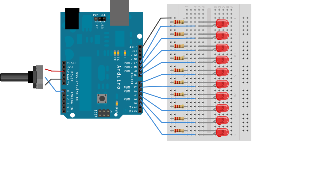
image developed using Fritzing. For more circuit examples, see the Fritzing project page
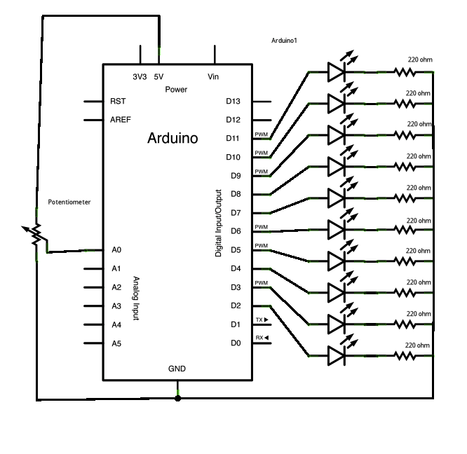
Schematic:
click the image to enlarge
Code
LED bar graph
Turns on a series of LEDs based on the value of an analog sensor.
This is a simple way to make a bar graph display. Though this graph
uses 10 LEDs, you can use any number by changing the LED count
and the pins in the array.
This method can be used to control any series of digital outputs that
depends on an analog input.
The circuit:
* LEDs from pins 2 through 11 to ground
created 4 Sep 2010
by Tom Igoe
This example code is in the public domain.
http://arduino.cc/en/Tutorial/BarGraph
*/
// these constants won't change:
const int analogPin = A0; // the pin that the potentiometer is attached to
const int ledCount = 10; // the number of LEDs in the bar graph
int ledPins[] = {
2, 3, 4, 5, 6, 7,8,9,10,11 }; // an array of pin numbers to which LEDs are attached
void setup() {
// loop over the pin array and set them all to output:
for (int thisLed = 0; thisLed < ledCount; thisLed++) {
pinMode(ledPins[thisLed], OUTPUT);
}
}
void loop() {
// read the potentiometer:
int sensorReading = analogRead(analogPin);
// map the result to a range from 0 to the number of LEDs:
int ledLevel = map(sensorReading, 0, 1023, 0, ledCount);
// loop over the LED array:
for (int thisLed = 0; thisLed < ledCount; thisLed++) {
// if the array element's index is less than ledLevel,
// turn the pin for this element on:
if (thisLed < ledLevel) {
digitalWrite(ledPins[thisLed], HIGH);
}
// turn off all pins higher than the ledLevel:
else {
digitalWrite(ledPins[thisLed], LOW);
}
}
}
See Also:
pinMode()for()digitalWrite()if...elsemap()- For Loop - Control multiple LEDs with a For Loop.
- Array - a variation on the For Loop example that demonstrates how to use an array.
- If Statement - how to use an if statement to change output conditions based on changing input conditions.
- Row Column Scanning - how to control an 8x8 matrix of LEDs.