Learning Examples | Foundations | Hacking | Links
Arduino Software Serial Interface
Note: If you just want to use a software serial interface, see the SoftwareSerial library included with Arduino 0007 and later. Read on if you'd like to know how that library works.
In this tutorial you will learn how to implement Asynchronous serial communication on the Arduino in software to communicate with other serial devices. Using software serial allows you to create a serial connection on any of the digital i/o pins on the Arduino. This should be used when multiple serial connections are necessary. If only one serial connection is necessary the hardware serial port should be used. This is a general purpose software tutorial, NOT a specific device tutorial. A tutorial on communicating with a computer is here. Device specific tutorials are on the Tutorial Page. For a good explanation of serial communication see Wikipedia. The software serial connection can run at 4800 baud or 9600 baud reliably.
Functions Available:
SWread(); Returns a byte long integer value from the software serial connection
Example:
byte RXval;
RXval = SWread();
SWprint(); Sends a byte long integer value out the software serial connection
Example:
byte TXval = 'h';
byte TXval2 = 126;
SWprint(TXval);
SWprint(TXval2);
Definitions Needed:
#define bit9600Delay 84
#define halfBit9600Delay 42
#define bit4800Delay 188
#define halfBit4800Delay 94
These definitions set the delays necessary for 9600 baud and 4800 baud software serial operation.
Materials needed:
- Device to communicate with
- Solderless breadboard
- Hookup wire
- Arduino Microcontroller Module
- Light emitting Diode (LED) - optional, for debugging
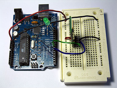
Prepare the breadboard
Insert the device you want to communicate with in the breadboard. Connect ground on the breadboard to ground from the microcontroller. If your device uses 5v power connect 5v from the microcontoller to 5v on the breadboard. Otherwise connect power and ground from an alternate power source to the breadboard in the same fashion. Make any other connections necessary for your device. Additionally you may want to connect an LED for debugging purposes between pin 13 and Ground.
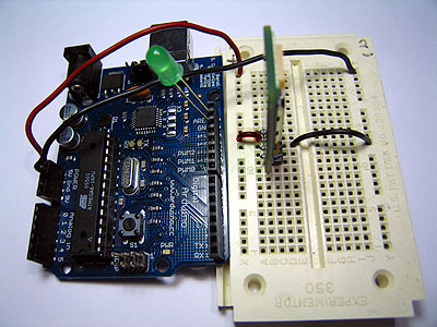
Decide which pins you want to use for transmitting and receiving. In this example we will use pin 7 for transmitting and pin 6 for receiving, but any of the digital pins should work.
Program the Arduino
Now we will write the code to enable serial data communication. This program will simply wait for a character to arrive in the serial recieving port and then spit it back out in uppercase out the transmit port. This is a good general purpose serial debugging program and you should be able to extrapolate from this example to cover all your basic serial needs. We will walk through the code in small sections.
#include <ctype.h>

#define bit9600Delay 84
#define halfBit9600Delay 42
#define bit4800Delay 188
#define halfBit4800Delay 94
Here we set up our pre-processor directives. Pre-processor directives are processed before the actual compilation begins. They start with a "#" and do not end with semi-colons.
First we include the file ctype.h in our application. This gives us access to the toupper() function from the Character Operations C library which we will use later in our main loop. This library is part of the Arduino install, so you don't need to do anything other than type the #include line in order to use it. Next we establish our baudrate delay definitions. These are pre-processor directives that define the delays for different baudrates. The #define bit9600Delay 84 line causes the compiler to substitute the number 84 where ever it encounters the label "bit9600Delay". Pre-processor definitions are often used for constants because they don't take up any program memory space on the chip.
byte rx = 6;
byte tx = 7;
byte SWval;
Here we set our transmit (tx) and recieve (rx) pins. Change the pin numbers to suit your application. We also allocate a variable to store our recieved data in, SWval.
void setup() {
  pinMode(rx,INPUT);
  pinMode(tx,OUTPUT);
  digitalWrite(tx,HIGH);
  digitalWrite(13,HIGH); //turn on debugging LED
  SWprint('h');  //debugging hello
  SWprint('i');
  SWprint(10); //carriage return
}
Here we initialize the lines, turn on our debugging LED and print a debugging message to confirm all is working as planned. We can pass inidvidual characters or numbers to the SWprint function.
void SWprint(int data)
{
  byte mask;
  //startbit
  digitalWrite(tx,LOW);
  delayMicroseconds(bit9600Delay);
  for (mask = 0x01; mask>0; mask <<= 1) {
    if (data & mask){ // choose bit
     digitalWrite(tx,HIGH); // send 1
    }
    else{
     digitalWrite(tx,LOW); // send 0
    }
    delayMicroseconds(bit9600Delay);
  }
  //stop bit
  digitalWrite(tx, HIGH);
  delayMicroseconds(bit9600Delay);
}
This is the SWprint function. First the transmit line is pulled low to signal a start bit. Then we itterate through a bit mask and flip the output pin high or low 8 times for the 8 bits in the value to be transmitted. Finally we pull the line high again to signal a stop bit. For each bit we transmit we hold the line high or low for the specified delay. In this example we are using a 9600 baudrate. To use 4800 simply replace the variable bit9600Delay with bit4800Delay.
int SWread()
{
  byte val = 0;
  while (digitalRead(rx));
  //wait for start bit
  if (digitalRead(rx) == LOW) {
    delayMicroseconds(halfBit9600Delay);
    for (int offset = 0; offset < 8; offset++) {
     delayMicroseconds(bit9600Delay);
     val |= digitalRead(rx) << offset;
    }
    //wait for stop bit + extra
    delayMicroseconds(bit9600Delay);
    delayMicroseconds(bit9600Delay);
    return val;
  }
}
This is the SWread function. This will wait for a byte to arrive on the recieve pin and then return it to the allocated variable. First we wait for the recieve line to be pulled low. We check after a half bit delay to make sure the line is still low and we didn't just recieve line noise. Then we iterate through a bit mask and shift 1s or 0s into our output byte based on what we recieve. Finally we allow a pause for the stop bit and then return the value.
void loop()
{
    SWval = SWread();
    SWprint(toupper(SWval));
}
Finally we implement our main program loop. In this program we simply wait for characters to arrive, change them to uppercase and send them back. This is always a good program to run when you want to make sure a serial connection is working properly.
For lots of fun serial devices check out the Sparkfun online catalog. They have lots of easy to use serial modules for GPS, bluetooth, wi-fi, LCDs, etc.
For easy copy and pasting the full program text of this tutorial is below:
//Created August 15 2006
//Heather Dewey-Hagborg
//http://arduino.cc

#include <ctype.h>

#define bit9600Delay 84
#define halfBit9600Delay 42
#define bit4800Delay 188
#define halfBit4800Delay 94

byte rx = 6;
byte tx = 7;
byte SWval;

void setup() {
  pinMode(rx,INPUT);
  pinMode(tx,OUTPUT);
  digitalWrite(tx,HIGH);
  digitalWrite(13,HIGH); //turn on debugging LED
  SWprint('h');  //debugging hello
  SWprint('i');
  SWprint(10); //carriage return
}

void SWprint(int data)
{
  byte mask;
  //startbit
  digitalWrite(tx,LOW);
  delayMicroseconds(bit9600Delay);
  for (mask = 0x01; mask>0; mask <<= 1) {
    if (data & mask){ // choose bit
     digitalWrite(tx,HIGH); // send 1
    }
    else{
     digitalWrite(tx,LOW); // send 0
    }
    delayMicroseconds(bit9600Delay);
  }
  //stop bit
  digitalWrite(tx, HIGH);
  delayMicroseconds(bit9600Delay);
}

int SWread()
{
  byte val = 0;
  while (digitalRead(rx));
  //wait for start bit
  if (digitalRead(rx) == LOW) {
    delayMicroseconds(halfBit9600Delay);
    for (int offset = 0; offset < 8; offset++) {
     delayMicroseconds(bit9600Delay);
     val |= digitalRead(rx) << offset;
    }
    //wait for stop bit + extra
    delayMicroseconds(bit9600Delay);
    delayMicroseconds(bit9600Delay);
    return val;
  }
}

void loop()
{
    SWval = SWread();
    SWprint(toupper(SWval));
}
code and tutorial by Heather Dewey-Hagborg