Learning Examples | Foundations | Hacking | Links
Examples > Stepper Library
Stepper Motor Knob
Stepper motors, due to their unique design, can be controlled to a high degree of accuracy without any feedback mechanisms. The shaft of a stepper, mounted with a series of magnets, is controlled by a series of electromagnetic coils that are charged positively and negatively in a specific sequence, precisely moving it forward or backward in small "steps".
There are two types of steppers, Unipolars and Bipolars, and it is very important to know which type you are working with. For more information about the differences of the two types, and about the circuits that must be built to control a stepper, please take a look at Tom Igoe's page on stepper motors.
In this example, the turns of a potentiometer (or other sensor) on analog input 0 are used to control the movement of a stepper motor while using the Arduino Stepper Library. The unipolar or bipolar stepper is controlled by using digital pins 8, 9, 10, and 11 in conjunction with either a U2004 Darlington Array (for unipolar steppers) or a SN754410NE H-Bridge (for bipolars).
Hardware Required
- Arduino Board
- potentiometer
- stepper motor
- U2004 Darlington Array (if using a unipolar stepper)
- SN754410ne H-Bridge (if using a bipolar stepper)
- power supply appropriate for your particular stepper
- breadboard
- hookup wire
Circuits
Below you'll find circuits for both unipolar and bipolar steppers. In either case, it is best to power your stepper motors from an external supply, as they draw too much to be powered directly from your Arduino board.
In both circuits, connect a 10k pot to power and ground, with it's wiper outputting to analog pin 0.
Note: Both circuits below are four wire configurations. Two wire configurations will not work with the code provided.
Unipolar Stepper Circuit
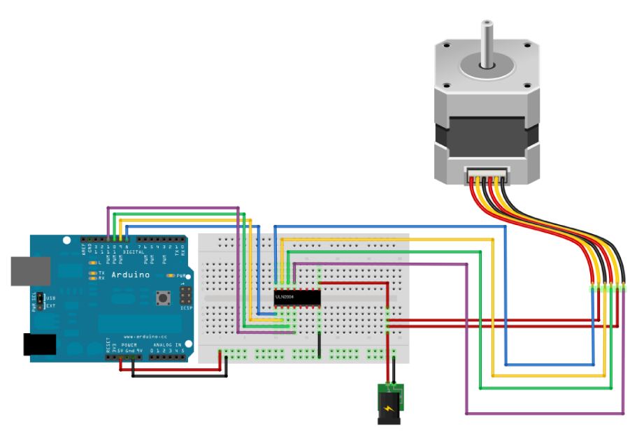
image developed using Fritzing. For more circuit examples, see the Fritzing project page
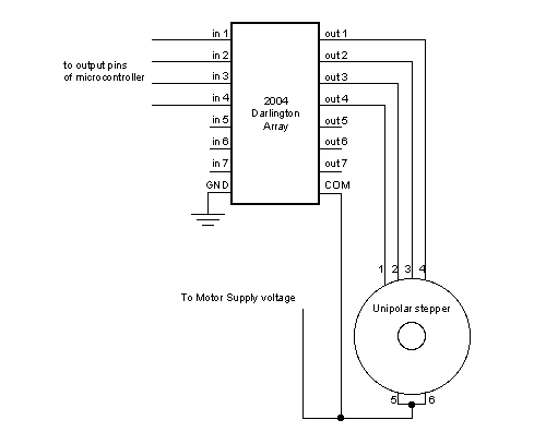
Unipolar Circuit Schematic
Bipolar Stepper Circuit
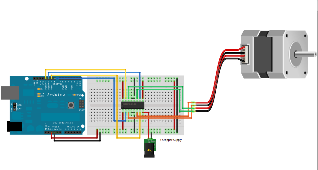
image developed using Fritzing. For more circuit examples, see the Fritzing project page
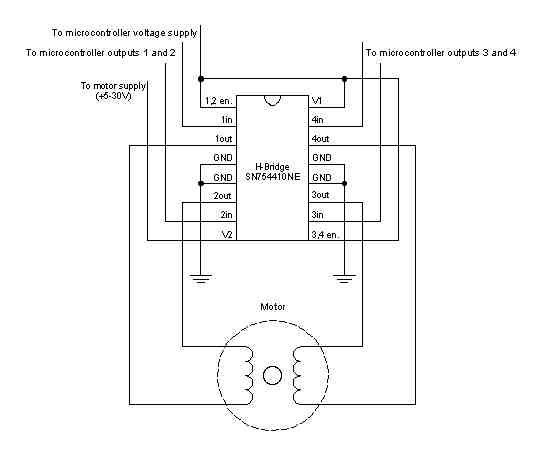
Bipolar Stepper Schematic
Code
(for both circuits)
* MotorKnob
*
* A stepper motor follows the turns of a potentiometer
* (or other sensor) on analog input 0.
*
* http://arduino.cc/en/Reference/Stepper
* This example code is in the public domain.
*/
#include <Stepper.h>
// change this to the number of steps on your motor
#define STEPS 100
// create an instance of the stepper class, specifying
// the number of steps of the motor and the pins it's
// attached to
Stepper stepper(STEPS, 8, 9, 10, 11);
// the previous reading from the analog input
int previous = 0;
void setup()
{
// set the speed of the motor to 30 RPMs
stepper.setSpeed(30);
}
void loop()
{
// get the sensor value
int val = analogRead(0);
// move a number of steps equal to the change in the
// sensor reading
stepper.step(val - previous);
// remember the previous value of the sensor
previous = val;
}
See also
Stepper myStepper = Stepper(steps, pin1, pin2, pin3, pin4)stepper.setSpeed()stepper.step()- Stepper library reference
- Sweep - sweep the shaft of a servo motor back and forth.
- Knob - control the position of a servo with a potentiometer.