Learning Examples | Foundations | Hacking | Links
Examples > Wire Library
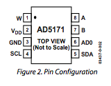
AD5171 Digital Potentiometer
This example shows how to control a Analog Devices AD5171 Digital Potentiometer which communicates via the I2C synchronous serial protocol. Using Arduino's I2C Wire Library, the digital pot will step through 64 levels of resistance, fading an LED.
The I2C protocol involves using two lines to send and receive data: a serial clock pin (SCL) that the Arduino pulses at a regular interval, and a serial data pin (SDA) over which data is sent between the two devices. As the clock pulse changes from low to high (known as the rising edge of the clock), a bit of information containing the address of a specific device and a request for data, is transferred from the Arduino to the I2C device over the SDA line. When the clock pin changes from high to low (the falling edge of the clock), the called upon device transmits it's data back to the Arduino over the same line.
Because the 12C protocol allows for each enabled device to have it's own unique address, and as both master and slave devices to take turns communicating over a single line, it is possible for your Arduino to communicate with many different devices (in turn) while using just two pins of your microcontroller.
Hardware Required
- Arduino Board
- AD5171 Digital Pot
- LED
- (1) 220 ohm resistor
- (2) 4.7K ohm resistors
- breadboard
- hook-up wire
Circuit
Connect pins 3, 6, and 7 of the AD5171 to GND, and pins 2 and 8 to +5V.
Connect pin 4, the digital pot's clock pin (SCL), to analog pin 5 on the Arduino, and pin 5, the data line (SDA), to analog pin 4. On both the SCL and SDA lines, add 4.7K ohm pull up resistors, connecting both lines to +5 V.
Finally, wire an LED to pin 1, the AD5171's "wiper", with a 220 ohm LED in series.
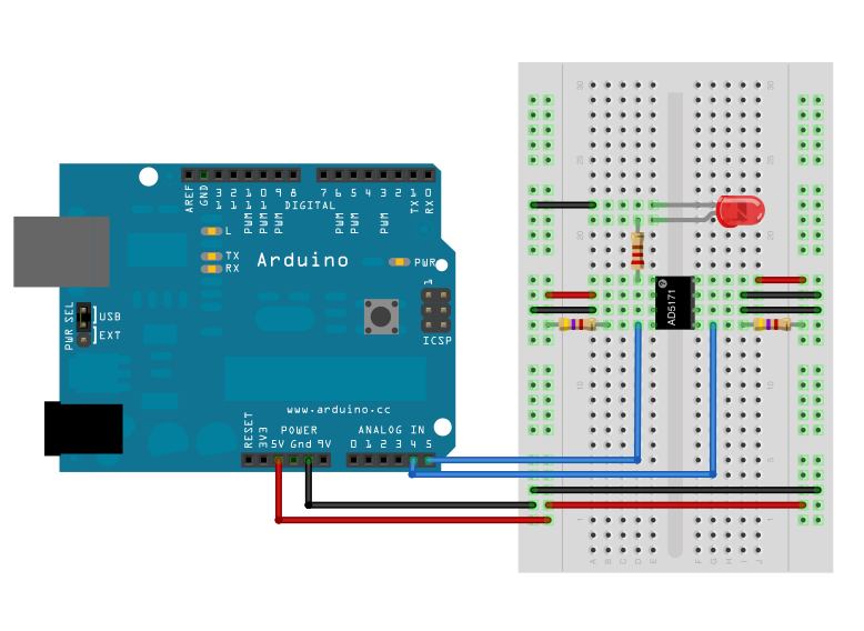
image developed using Fritzing. For more circuit examples, see the Fritzing project page
When the AD5171's pin 6, ADO, is connected to ground, it's address is is 44. To add another digital pot to the same SDA bus, connect the second pot's ADO pin to +5V, changing it's address to 45.
You can only use two of these digital potentiometers simultaneously.
Schematic

Code
// by Nicholas Zambetti <http://www.zambetti.com>
// and Shawn Bonkowski <http://people.interaction-ivrea.it/s.bonkowski/>
// Demonstrates use of the Wire library
// Controls AD5171 digital potentiometer via I2C/TWI
// Created 31 March 2006
// This example code is in the public domain.
// This example code is in the public domain.
#include <Wire.h>
void setup()
{
Wire.begin(); // join i2c bus (address optional for master)
}
byte val = 0;
void loop()
{
Wire.beginTransmission(44); // transmit to device #44 (0x2c)
// device address is specified in datasheet
Wire.write(byte(0x00)); // sends instruction byte
Wire.write(val); // sends potentiometer value byte
Wire.endTransmission(); // stop transmitting
val++; // increment value
if(val == 64) // if reached 64th position (max)
{
val = 0; // start over from lowest value
}
delay(500);
}